Programmable Logic with CPLDs
Why CPLDs?
CPLDs (Complex Programmable Logic Devices) are versatile chips that replaced PLDs and PALs in the late 80s and 90s.
Although they are an older technology with old development environments, CPLDs are significantly easier to integrate into a project than FPGAs. CPLDs are still readily available and can be a convenient option for building "retro" electronics projects while being a lot closer to period-correct than a modern FPGA.
If you are just looking to learn programmable logic, I highly recommend buying a modern FPGA development board such as the Cmod S7 and Cmod A7, which are cheap devices that can be plugged into a breadboard. The NEXYS A7 is another good option with lots of features, including VGA, Ethernet, and USB.
Getting Started
Required Hardware
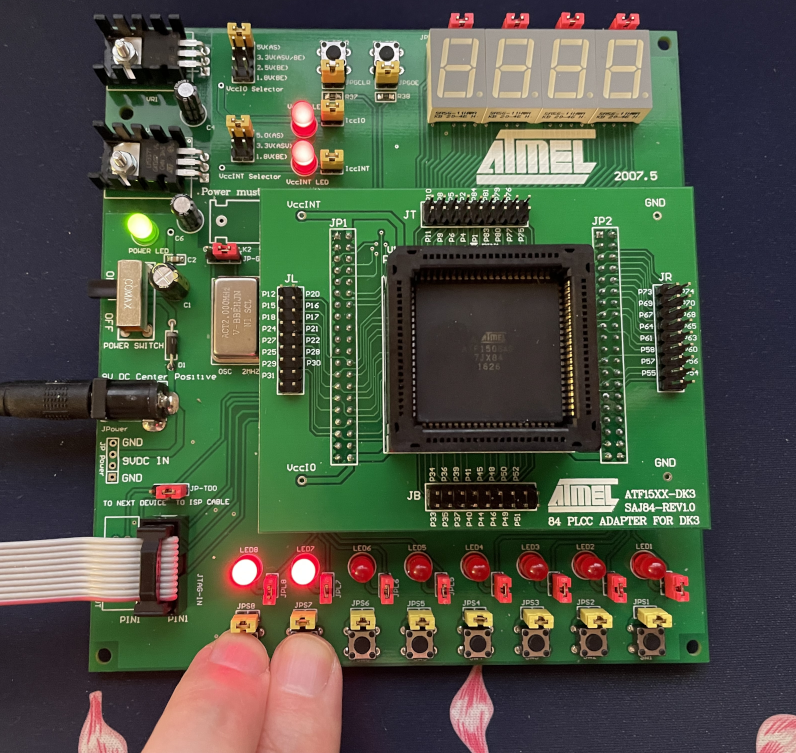
Today we will be working with the Microchip ATF1508A CPLD and the ATF15XX-DK3-U development kit.
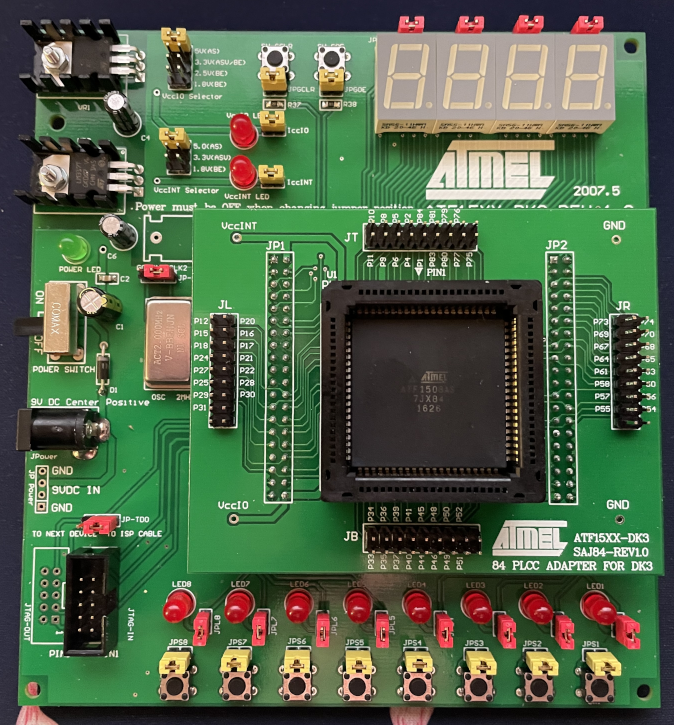
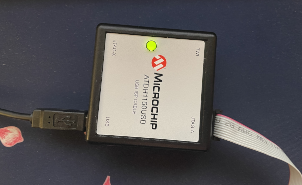
The JTAG programmer included in the kit (ATDH1150USB) can be used for in-system programming and will be useful in future projects.
Do note that the development kit includes a couple entirely random ATF15XX series CPLDs and they are not necessarily the right package for the adapter included in the kit!
We will be using the following:
- ATF15XX-DK3-U Development Kit
- ATF15XXDK3-SAJ84 PLCC-84 Adapter
- ATF1508A-7JX84 PLCC-84 CPLD
WinCupl
Microchip provides WinCupl as the primary tool for designing logic for their CPLDs. It's based on a Hardware Description Language (HDL) called CUPL (Compiler for Universal Programmable Logic), which was designed during the 80s. While WinCupl does provide an editing environment, we'll rely on the command-line tools it provides rather than working in the software directly.
You can download WinCupl from the Microchip website:
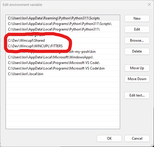
When installing WinCupl, it's important to understand that it doesn't cope with spaces in the directory. I recommend keeping things simple. For example, I have it installed to C:\Dev\Wincupl. For the rest of this article I will just assume you are also using this path or will make adjustments to my instructions as necessary.
You will need make sure the directories C:\Dev\Wincupl\Shared and C:\Dev\Wincupl\WINCUPL\FITTERS are added to your PATH if the installer didn't already do this for you.
ATMISP
ATMISP takes the compiled output of our logic and programs them into the CPLD.
You can download ATMISP v7.3 from the Microchip website:
I've installed this adjacent to WinCupl at C:\Dev\ATMISP7.
Visual Studio Code
You're probably already familiar with VS Code, which is the tool we'll be using for our development. While you're welcome to use your own editor, note that we'll be adding tasks to our project to simplify compiling and simulating.
You will also want to install the CUPL Language Support extension.
Blinky Lights
Lets start with the "Hello World" of programmable logic. We are going to wire the buttons on the development board to turn on the lights directly above them.
Setup
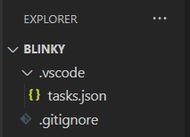
Start by creating a folder to store our work. Lets call it blinky.
We are going to leverage VS Code tasks to run the cupl.exe compiler for our project. Inside our blinky folder, create a .vscode directory, and under that a tasks.json file.
{
    // See https://go.microsoft.com/fwlink/?LinkId=733558
    // for the documentation about the tasks.json format
    "version": "2.0.0",
    "tasks": [
        {
            "label": "cupl",
            "type": "shell",
            "command": "cupl.exe -m1jnlx -u C:\\Dev\\Wincupl\\Shared\\Atmel.DL ${fileDirname}\\${fileBasenameNoExtension}.pld",
            "group": "build",
            "options": {
                "cwd": "${fileDirname}"
            }
        },
        {
            "label": "cupl + sim",
            "type": "shell",
            "command": "cupl.exe -m1jnlxs -u C:\\Dev\\Wincupl\\Shared\\Atmel.DL ${fileDirname}\\${fileBasenameNoExtension}.pld",
            "group": "build",
            "options": {
                "cwd": "${fileDirname}"
            }
        }
    ]
}
The cupl Task will run just the compiler itself. The cupl + sim task will compile and run the simulator, which will let us perform input/output tests on our logic.
The cupl compiler will generate a bunch of files, most of which we plan to ignore. If you are using Git, you may also want to create a .gitignore file.
*.lst
*.mx
*.pdf
*.pla
*.so
*.wo
*.abs
*.pdf
*.tt*
*.vt
*.doc
*.plc
*.fit
*.rpt
*.tmv
*.sim
*.jed
*.pin
jtag.log
syndos.env
CM*
!CM*.*
CB*
!CB*.*
Writing Logic
Source Code available on GitHub.
Now that we have a basic project folder in place, we are going to create a file with our logic called blinky.pld.
Lets start by adding a header and a little structure for our code:
/* Headers */
Name     blinky;
PartNo   00;
Date     4/17/2023;
Revision 01;
Designer Lori Holden;
Company  None;
Assembly None;
Location ;
Device   f1508ispplcc84;

/* Configure cupl */
PROPERTY ATMEL {PIN_KEEP = OFF};
PROPERTY ATMEL {SECURITY = OFF};
PROPERTY ATMEL {POWER_RESET = ON};
PROPERTY ATMEL {PIN_KEEP = OFF};
PROPERTY ATMEL {LOGIC_DOUBLING = OFF};
PROPERTY ATMEL {TDI_PULLUP = ON};
PROPERTY ATMEL {TMS_PULLUP = ON};
PROPERTY ATMEL {CASCADE_LOGIC = ON};
PROPERTY ATMEL {OUTPUT_FAST = ON};
PROPERTY ATMEL {PREASSIGN = YES};

/* Inputs */

/* Outputs */

/* Logic */
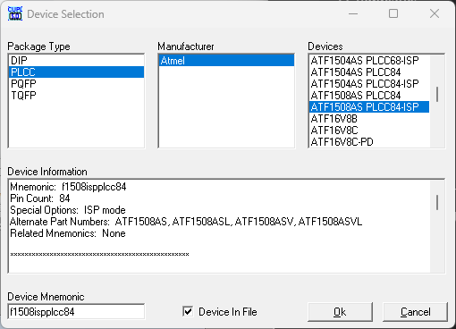
While most of the header is boilerplate, it's important to pay attention to the Device specifier. This information is crucial for cupl to determine how to optimize our logic to fit our specific CPLD. It's essential to ensure that the device specified matches the actual CPLD we're using on our development board. In this particular case, we're using the ATF1508 in a PLCC84 package and intend to use "In-system programming."
To obtain a list of available devices, you can run the WinCupl GUI and navigate to Devices in the Options menu.
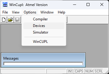
This will get you a Device Selection screen, where you can lookup your CPLD to get the actual Mnemonic that should be used in the header.
Next, we should define our pin assignments. These are physically mapped on the development board by the adapter and must match exactly. The User Guide complete listing of all the pins and where they map to.
/* Inputs */
// Push-button Switches
PIN 54=SWA;
PIN 51=SWB;
PIN 49=SWC;
PIN 44=SWD;
PIN 9=SWE;
PIN 6=SWF;
PIN 4=SWG;
PIN 80=SWH;

/* Outputs */
// LEDs
PIN 69=LED1;
PIN 67=LED2;
PIN 64=LED3;
PIN 60=LED4;
PIN 27=LED5;
PIN 24=LED6;
PIN 18=LED7;
PIN 15=LED8;
We can now write some glue logic to wire each button with the LED directly above it.
/* Logic */
LED1=SWA;
LED2=SWB;
LED3=SWC;
LED4=SWD;
LED5=SWE;
LED6=SWF;
LED7=SWG;
LED8=SWH;
We should now have everything in place to start a compile. Lets take advantage of the cupl task we created earlier by pressing ctrl+shift+b (or selecting Terminal/Run Build Task from the menu) and selecting the cupl task.
 *  Executing task: cupl.exe -m1jnlx -u C:\Dev\Wincupl\Shared\Atmel.DL C:\Users\lori\Projects\Blinky\blinky.pld

cuplx
time: 0 secs
cupla
time: 0 secs
cuplb
time: 0 secs
cuplm
time: 0 secs
cuplc
time: 0 secs
find1508
time: 1 secs
total time: 1 secs


Normal exit
Error Code = 0
Assuming everything has gone correctly, the compiler will have generated a large number of files. Of interest is the blinky.fit file, which has the output from the fitter.
Simulation
With the simulator, we'll be able to define a set of test vectors, which will enable us to simulate different values on our input pins and measure the results on our output pins. Although our "blinky" project doesn't involve interesting or complex logic, we'll use this opportunity to learn how to use the simulator.
Create a blinky.si file with the following contents:
Name     blinky;
PartNo   00;
Date     4/17/2023;
Revision 01;
Designer Lori Holden;
Company  None;
Assembly None;
Location ;
Device   f1508ispplcc84;

ORDER: SWA, SWB, SWC, SWD, SWE, SWF, SWG, SWH, LED1, LED2, LED3, LED4, LED5, LED6, LED7, LED8;

VECTORS:
0 0 0 0 0 0 0 0 L L L L L L L L
1 1 1 1 1 1 1 1 H H H H H H H H
1 0 0 0 0 0 0 0 L L L L L L L L
The header is identical to the one we created for blinky.pld.
ORDER: specifies the order we will be specifying our pins (inputs and outputs) in our test vectors.
VECTORS: is a list of test vectors. The inputs and outputs are specified a bit differently from each other. In our example, the inputs are 0 and 1, and the outputs are L and H. Note the extra newline at the end of the vectors! Without this, our last vector will not be processed.
The keen eyed will notice that our test vectors should generate an error. We can run our simulation with the cupl + sim task.
time: 0 secs
Total time: 0 secs

CSIM errors encountered!
Normal exit
Error Code = 1
The simulator doesn't output any diagnostic information to the command line, so we must look at the simulator output file for this. In our case, we can open blinky.so and see where the simulator failed.
=========================
              LLLLLLLL
      SSSSSSSSEEEEEEEE
      WWWWWWWWDDDDDDDD
      ABCDEFGH12345678
=========================
0001: 00000000LLLLLLLL
0002: 11111111HHHHHHHH
0003: 10000000HLLLLLLL
              ^
[0019sa] user expected (L) for LED1
We can see that the simulator is telling us that we specified a 1 input, but are expecting a L result. In this case, pressing a button should turn on the light, so lets modify the expected result to H and it should succeed.
time: 0 secs
total time: 0 secs


Normal exit
Error Code = 0
Please Note, there is a known bug with the simulator that generates messages similar to the following. This can be safely ignored.
[0033sa] Please note: jedec vectors cannot be created with undefined pin numbers
Programming our CPLD
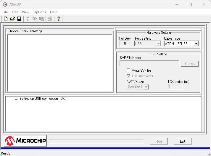
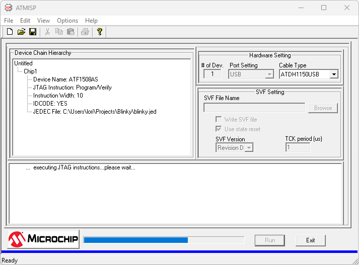
Load up ATMISP and create a new "Device Chain". This is done with the "New" button. (Do not bother to save)
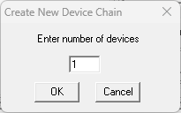
This is the "chain of JTAG devices". If you have a bunch of devices wired up together for in-system programming you will need to worry about this value. Our development board just has a single device, so you should leave it as 1.
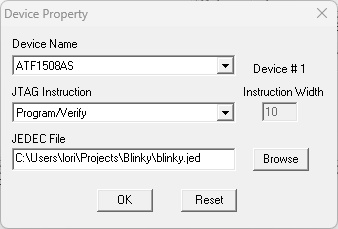
Our ATF1508AS device should already be selected for us.
In JTAG Instruction, select the option for Program/Verify.
Under JEDEC File, hit Browse and locate the blinky.jed we created when we compiled the project.
At this point, it's time to program our device! Click the Run button.
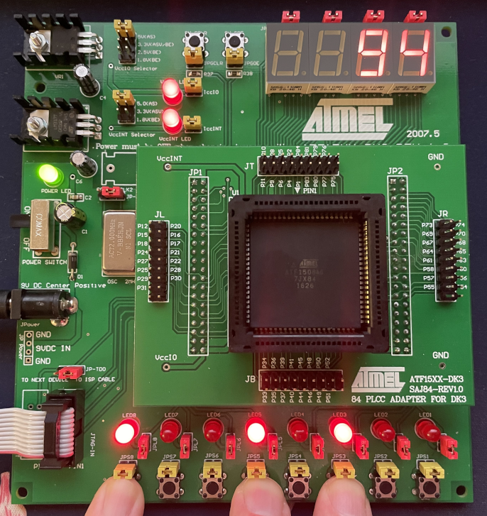
Assuming everything has gone correctly, we should now be able to turn on the lights by pressing the buttons!
Binary to Hex Display
Source Code available on GitHub.
Lets create a new project that converts a binary number entered with the buttons into a hex value on our display.
Create a new folder called hex and copy over our .vscode folder and .gitignore file from the blinky project.
Then create a new file hex.pld with the following contents:
/* Headers */
Name     hex;
PartNo   00;
Date     4/17/2023;
Revision 01;
Designer Lori Holden;
Company  None;
Assembly None;
Location ;
Device   f1508ispplcc84;

/* Configure cupl */
PROPERTY ATMEL {PIN_KEEP = OFF};
PROPERTY ATMEL {SECURITY = OFF};
PROPERTY ATMEL {POWER_RESET = ON};
PROPERTY ATMEL {PIN_KEEP = OFF};
PROPERTY ATMEL {LOGIC_DOUBLING = OFF};
PROPERTY ATMEL {TDI_PULLUP = ON};
PROPERTY ATMEL {TMS_PULLUP = ON};
PROPERTY ATMEL {CASCADE_LOGIC = ON};
PROPERTY ATMEL {OUTPUT_FAST = ON};
PROPERTY ATMEL {PREASSIGN = YES};

/* Inputs */
// Push-button Switches
PIN 54=SWA;
PIN 51=SWB;
PIN 49=SWC;
PIN 44=SWD;
PIN 9=SWE;
PIN 6=SWF;
PIN 4=SWG;
PIN 80=SWH;

/* Outputs */
// LEDs
PIN 69=LED1;
PIN 67=LED2;
PIN 64=LED3;
PIN 60=LED4;
PIN 27=LED5;
PIN 24=LED6;
PIN 18=LED7;
PIN 15=LED8;

// DSP 1
PIN 68=!DSP1A;
PIN 74=!DSP1B;
PIN 70=!DSP1C;
PIN 63=!DSP1D;
PIN 58=!DSP1E;
PIN 65=!DSP1F;
PIN 61=!DSP1G;
PIN 73=!DSP1DOT;

// DSP 2
PIN 52=!DSP2A;
PIN 57=!DSP2B;
PIN 55=!DSP2C;
PIN 48=!DSP2D;
PIN 41=!DSP2E;
PIN 50=!DSP2F;
PIN 45=!DSP2G;
PIN 56=!DSP2DOT;

/* Fields */
FIELD LSB=[SWD, SWC, SWB, SWA];
FIELD MSB=[SWH, SWG, SWF, SWE];

FIELD DSP1=[DSP1A, DSP1B, DSP1C, DSP1D, DSP1E, DSP1F, DSP1G];
FIELD DSP2=[DSP2A, DSP2B, DSP2C, DSP2D, DSP2E, DSP2F, DSP2G];

/* Logic */
LED1=SWA;
LED2=SWB;
LED3=SWC;
LED4=SWD;
LED5=SWE;
LED6=SWF;
LED7=SWG;
LED8=SWH;

TABLE LSB => DSP1 {
  //       abcdefg
  'h'0=>'b'1111110;
  'h'1=>'b'0110000;
  'h'2=>'b'1101101;
  'h'3=>'b'1111001;
  'h'4=>'b'0110011;
  'h'5=>'b'1011011;
  'h'6=>'b'1011111;
  'h'7=>'b'1110000;
  'h'8=>'b'1111111;
  'h'9=>'b'1111011;
  'h'A=>'b'1110111;
  'h'B=>'b'0011111;
  'h'C=>'b'1001110;
  'h'D=>'b'0111101;
  'h'E=>'b'1001111;
  'h'F=>'b'1000111;
}

TABLE MSB => DSP2 {
  //       abcdefg
  'h'0=>'b'1111110;
  'h'1=>'b'0110000;
  'h'2=>'b'1101101;
  'h'3=>'b'1111001;
  'h'4=>'b'0110011;
  'h'5=>'b'1011011;
  'h'6=>'b'1011111;
  'h'7=>'b'1110000;
  'h'8=>'b'1111111;
  'h'9=>'b'1111011;
  'h'A=>'b'1110111;
  'h'B=>'b'0011111;
  'h'C=>'b'1001110;
  'h'D=>'b'0111101;
  'h'E=>'b'1001111;
  'h'F=>'b'1000111;
}
Under Outputs, you'll notice that we've kept our LEDs from the previous project but added mappings for two of our displays. For a listing of pin mapping, refer to the ATF15xx-DK3-U Users Guide.
This project features a new section for "Fields." Fields enable us to combine bits to create a larger value. In this case, we have the Least Significant Bit (LSB) and Most Significant Bit (MSB) for our binary input number. Additionally, we've defined DSP1 and DSP2 for controlling two of our hex displays.
In the logic section, we've defined a set of tables, which we use to enable individual segments of our displays based on the input number.
To learn more about Fields and Tables, I recommend reading the CUPL Programmer's Reference.
Compile the project and program your CPLD just as we did previously!
Additionally, I encourage you to create test vectors and experiment with the tables.
Please note, I haven't found a way to make ATMISP detect updates to the JEDEC file each time it's compiled. Because of this, I usually create a new "Device Chain" every time I make changes.
FAQ
Are there alternatives to WinCupl?
Yep! Though, nothing that is actually current and actively maintained. There are two primary that I know of for the ATF15xx series chips:
- You can acquire a license for ProChip Designer. My understanding is that this software is quite old and isn't something Microchip can provide more than a time limited trial for.
- Quartus II 13.0 SP1 along with POF2JED. This is the last version of Quartus II to support the MAX 7000 series devices, which are directly compatible with Microchip/Atmel ATF15xx CPLDs. You convert the POF files generated by Quartus II to a JEDEC file that can be used by ATMISP7.